Aluminum Tube Supplier — 5083 / 6061 / 5052 / 5086 / 7005 | OD 6–500 mm, Wall 0.5–50 mm | Wall Verification & Hydrostatic Testing | ASTM B241 / EN 755 | EN 10204 3.1 | MOQ 500 kg | Quote in 24h
Aluminum Tube Wall Thickness & Pressure Rating: Selection Guide
Wall thickness is the single most consequential number on an aluminum tube drawing. Too thin, and the line bursts, buckles or erodes through. Too thick, and you pay for metal that adds weight without adding safety — on a boat or an aircraft, that weight compounds every hour of operation.
This guide gives you the complete selection method our engineers use: the working-pressure formula with a worked example, pressure lookup tables for common sizes, how temper and temperature change the answer, corrosion and erosion allowances, bend-radius rules, and a final pre-order checklist. Prefer us to run the numbers? Send your working pressure and media — we verify walls free of charge with every quote.
First, Get the Terms Right: OD, Wall, Schedule
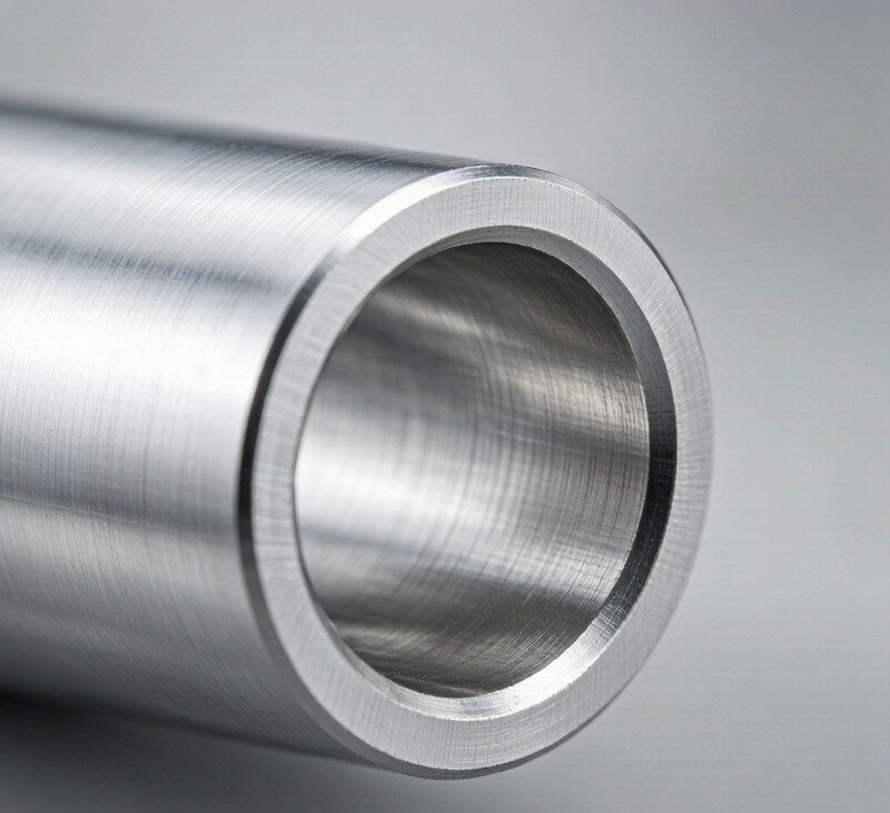
Outside diameter (OD) is the controlling dimension of tube. Wall thickness (t) sets strength and weight. Inside diameter (ID = OD − 2t) sets flow. These three numbers are linked: every strength calculation uses OD and t, every flow calculation uses ID.
Tube vs pipe: tube is ordered by OD × wall (engineering control); pipe is ordered by nominal size and schedule (Sch 10/40/80), where wall steps are coarse. Aluminum extruders work in true OD × wall, which is why tube is the normal aluminum product form — you specify exactly the metal you need instead of jumping between schedule walls.
Two tolerances matter for pressure: OD tolerance (typically ± 1% or less) and wall tolerance (typically ± 10% extruded). Always design against the minimum wall, not nominal: a 3.0 mm nominal wall at −10% tolerance carries 2.7 mm of metal. If that difference changes your result, order a tighter tolerance class — we supply ± 5% drawn tube and verified-wall extrusions.
The Working Pressure Formula (With a Worked Example)
For walls thinner than about 10% of OD — true for nearly all aluminum tube — the thin-wall hoop (Barlow) formula applies:
P = 2 · S · t / D
where P = allowable internal pressure, S = allowable stress = base-metal tensile strength ÷ safety factor, t = minimum wall, D = outside diameter.
Worked example: 5083-H112 round tube, OD 60.3 mm, nominal wall 3.0 mm (minimum 2.7 mm at −10%), tensile strength 275 MPa, safety factor 3:
• S = 275 / 3 ≈ 92 MPa
• P = 2 × 92 × 2.7 / 60.3 ≈ 8.2 MPa ≈ 82 bar allowable at room temperature
Three adjustments follow: derate for temperature (× 0.8 at 150 °C), add corrosion allowance to t if the media is seawater, and remember the rating assumes a seamless wall — a welded line in 6061-T6 must use the as-welded strength (~165 MPa) instead of 310 MPa. For thick-wall tube (t > 0.1·D) the Lamé/medium-wall formulas apply — send us that case and we will calculate it.
Pressure Lookup Table: 6061-T6 Tube (SF = 4)
| OD (mm) | Wall 1.5 mm | Wall 2.0 mm | Wall 3.0 mm | Wall 5.0 mm | Wall 8.0 mm |
|---|---|---|---|---|---|
| 12 | 96 bar | 128 bar | 192 bar | — | — |
| 16 | 72 bar | 96 bar | 144 bar | — | — |
| 25 | 46 bar | 61 bar | 91 bar | 152 bar | — |
| 38 | 30 bar | 40 bar | 60 bar | 100 bar | — |
| 50 | 23 bar | 31 bar | 46 bar | 76 bar | 122 bar |
| 76 | — | 20 bar | 30 bar | 50 bar | 80 bar |
| 102 | — | 15 bar | 23 bar | 38 bar | 60 bar |
| 152 | — | — | 15 bar | 25 bar | 41 bar |
| 203 | — | — | 11 bar | 19 bar | 30 bar |
Basis: 6061-T6 tensile 310 MPa, safety factor 4 → S = 77.5 MPa; P = 2·S·t/D. Values are theoretical room-temperature ratings for seamless tube — subtract for temperature, corrosion, fittings and welded joints. At SF = 3 the same walls carry 33% more pressure; most industrial specs use SF 3–4.
Pressure Lookup Table: 5083-H112 Tube (SF = 3, Marine Use)
| OD (mm) | Wall 2.0 mm | Wall 3.0 mm | Wall 4.0 mm | Wall 6.0 mm | Wall 10.0 mm |
|---|---|---|---|---|---|
| 25 | 73 bar | 110 bar | — | — | — |
| 38 | 48 bar | 72 bar | — | — | — |
| 50 | 37 bar | 55 bar | 73 bar | — | — |
| 60.3 | 30 bar | 45 bar | 60 bar | — | — |
| 76 | 24 bar | 36 bar | 48 bar | 72 bar | — |
| 102 | — | 27 bar | 36 bar | 54 bar | 90 bar |
| 159 | — | — | 23 bar | 35 bar | 58 bar |
| 219 | — | — | 17 bar | 25 bar | 42 bar |
| 273 | — | — | 14 bar | 21 bar | 34 bar |
Basis: 5083-H112 tensile 275 MPa, SF 3 → S ≈ 92 MPa. These ratings suit seawater cooling, fuel transfer and low/medium-pressure hydraulic duty with the corrosion allowances discussed below. Higher tempers (H116/H321, tensile to 385 MPa) lift the same geometries by ~30%. For welded marine systems, pair these tables with the velocity and galvanic rules in our marine piping guide.
How Temper and Welding Change the Rating
| Alloy / Condition | Tensile (MPa) | Relative Pressure Capacity |
|---|---|---|
| 5083-O | 275 | 0.89× (reference = H112) |
| 5083-H112 | 275 – 350 | 1.00× |
| 5083-H116 / H321 | 305 – 385 | 1.15 – 1.30× |
| 6061-T6 / T651 (seamless) | ≥ 310 | 1.30× (vs 5083-H112) |
| 6061-T6 welded (HAZ) | ~165 | 0.70× — rate welded lines on this |
| 7005-T53 welded (HAZ) | ~280 | 1.05× — best welded strength |
The two rows that surprise buyers most: welded 6061-T6 loses about 40% of its capacity in the heat-affected zone, so a welded 6061 line is often weaker than a welded 5083 line of the same size; and 7005 holds the best as-welded strength of all weldable aluminum alloys, which is why it appears in high-load welded frames. Temper designation refresher in our temper designations guide; alloy trade-offs in the 5083 vs 6061 comparison.
Corrosion, Erosion & Temperature Allowances
| Service | Allowance to Add to Calculated Wall |
|---|---|
| Dry indoor / atmospheric | None (film keeps corrosion < 0.001 mm/yr) |
| Outdoor, weather-exposed | + 0.1 – 0.2 mm total (25-yr) |
| Continuous seawater flow ≤ 2 m/s | + 0.3 – 0.5 mm per side (25-yr design life) |
| Seawater 2 – 3 m/s or sediment-laden | + 0.5 – 1.0 mm per side, or epoxy lining |
| Fuel / oil / dry compressed air | None |
| Temperature 150 °C | Derate pressure capacity × 0.8 |
| Temperature 200 °C | Derate pressure capacity × 0.5 (avoid above 200 °C) |
The stacking rule: compute the structural wall from the pressure formula first, then add the service allowance to get the nominal wall you order. Example — seawater line needing 2.6 mm structural: order 3.5–4.0 mm nominal, so that after 25 years of service the remaining wall still exceeds the structural requirement. Never let the corrosion allowance substitute for the structural wall — they serve different failure modes.
Wall Thickness & Minimum Bend Radius
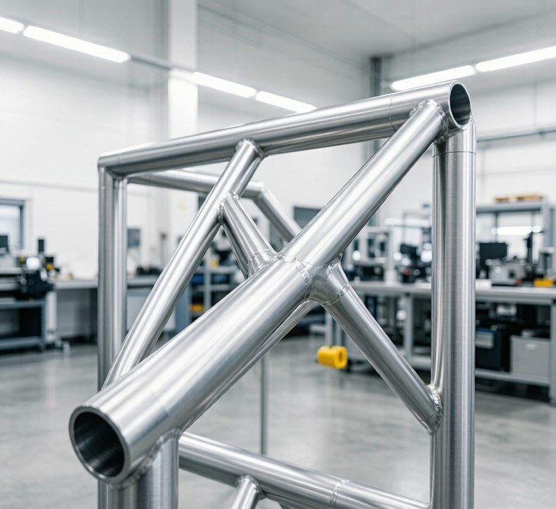
| Wall / OD Ratio (t/D) | 5083-O / H111 | 5083-H112 / H321 | 6061-T6 |
|---|---|---|---|
| ≥ 0.08 (thick) | 1.5 × OD | 2.0 × OD | 3.0 × OD (mandrel) |
| 0.04 – 0.08 | 2.0 × OD | 2.5 × OD | 3.5 – 4 × OD (mandrel) |
| 0.02 – 0.04 | 2.5 – 3 × OD | 3 – 4 × OD | Roll-form or buy T4 |
| < 0.02 (thin) | Mandrel + pressure die | Mandrel + pressure die | Not recommended |
Thicker walls bend tighter but weigh more — the classic optimization. Practical tips: bend with the weld seam (if any) at the neutral axis; support thin walls with mandrel and wiper dies to prevent wrinkling; expect 1–3° springback in 5083 and 3–5° in 6061-T6; and where geometry demands very tight radii, consider 5083-O tube and age nothing — it is not heat-treatable, so it keeps its formed properties. Full process detail in our bending & forming guide.
How HXM Verifies Wall & Pressure
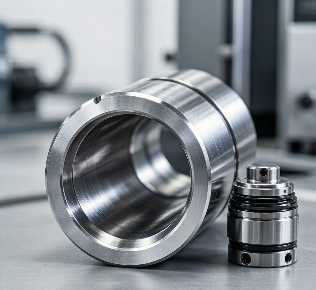
Our tube ships with verification at three levels:
• Dimensional: ultrasonic wall-thickness scanning on extruded lots, plus micrometer checks on OD and wall against the tolerance class you ordered (± 10% standard, ± 5% on request, verified-wall certification available).
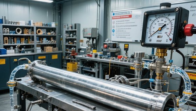
• Pressure: hydrostatic test at 1.5× agreed working pressure with hold time and witnessed certificates; pneumatic underwater testing where weight of water is impractical; burst testing to 4× working pressure for qualification lots.
• Material: EN 10204 3.1 mill certificates (chemistry + mechanicals) with every delivery; third-party inspection by SGS / TUV / BV on request; honed-bore cylinder tube measured to H8 with internal surface Ra documentation.
For specialty duty — honed hydraulic tube, structural 7005 frames, or weight calculations for shipping cost — our engineering desk supports the full verification chain.
Pre-Order Checklist & Stock Range
Before ordering, confirm these seven items — they cover 95% of wall-selection mistakes:
1. Working pressure (and test pressure policy) — in bar or MPa, at the point of use.
2. Media and temperature — decides corrosion allowance and derating.
3. Safety factor — your company standard or code (we default to 3–4).
4. Welded or seamless service — welded 6061 must be rated on HAZ strength.
5. Tolerance class — ± 10% standard, tighter if your margin is thin.
6. Bends and fittings — check radius against wall ratio above.
7. Certificates — EN 10204 3.1 standard; hydrostatic and third-party inspection on request.
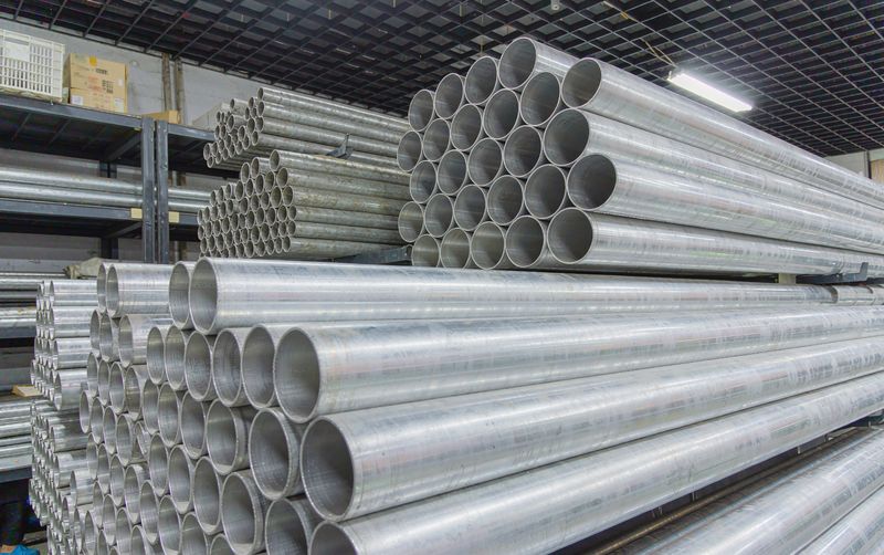
Stock range: 5083 / 6061 / 5052 / 5086 / 7005 tube, OD 6–500 mm, wall 0.5–50 mm, tempers O through T651/H321, lengths 1000–6000 mm with cut-to-length. MOQ 500 kg per size; stock ships 3–5 days, production 7–25 days. Product pages: 5083 · 6061 · 5052 · 5086 · 7005.
Frequently Asked Questions: Wall Thickness & Pressure Rating
How do I calculate the working pressure of an aluminum tube?
Use the thin-wall hoop (Barlow) formula: P = 2 · S · t / D, where P is allowable internal pressure, S the allowable stress of the alloy/temper (typically tensile strength ÷ safety factor), t the wall thickness and D the outside diameter. Example: 5083-H112 tube, OD 60.3 mm, wall 3 mm, allowable stress 90 MPa (≈ tensile 275 MPa ÷ SF 3) gives P = 2 × 90 × 3 / 60.3 ≈ 8.9 MPa (89 bar) theoretical. Real system ratings are then limited by fittings, codes and temperature — always verify with a 1.5× hydrostatic test.
What is the standard wall thickness tolerance for aluminum tube?
Extruded tube is typically supplied to ± 10% of nominal wall per ASTM B241 / EN 755 (exact class depends on wall and OD). Drawn tube can be held to ± 5% or better. If your pressure calculation is close to the limit, specify the tighter tolerance class on the order — and remember the minimum wall after tolerance, not the nominal, is what carries the load.
Does temper affect the pressure rating of aluminum tube?
Yes, directly. Working pressure scales with the strength you allow in the formula. For 60.3 × 3 mm tube, moving from 5083-O (tensile 275 MPa) to 5083-H321 (385 MPa) increases the allowable pressure by roughly 40%. Heat-treatable 6061-T6 behaves differently: welding locally anneals the heat-affected zone, so a welded line should be rated on the as-welded strength (roughly 165 MPa), not the T6 value.
How much corrosion allowance should I add to aluminum tube walls?
For atmospheric or dry service, essentially none — aluminum’s passive film keeps general corrosion below 0.001 mm/year. For continuous seawater service, 0.1–0.2 mm total general corrosion over 25 years is typical, but designers commonly add 0.3–0.5 mm per side to cover pitting statistical spread and erosion at flow velocities above 2 m/s. For fuel, oil, gas and compressed air, no corrosion allowance is needed.
What safety factor should I use for aluminum tube pressure design?
Common practice: 4:1 on tensile strength for general industrial lines, 3:1 for well-controlled static service, and 2.25–2.5:1 minimum per pressure-vessel style codes where inspection and testing are stringent. Marine class societies and hydraulic applications often add a burst test requirement of 4× working pressure. When in doubt, use 4:1 — the weight penalty of one extra wall step is small.
What is the minimum bend radius relative to wall thickness?
Thicker walls bend tighter. For 5083-O/H111 tube: minimum centerline radius ≈ 1.5–2× OD with a 2 mm+ wall, 2.5–3× OD below 1.5 mm wall. For 6061-T6: expect 3–4× OD with mandrel support, or buy T4 and age after forming. The relationship is non-linear — very thin walls wrinkle and ovalize, so below 1 mm wall use internal mandrel or pressure-die assisted rotary draw bending. Details in our bending & forming guide.
How is aluminum tube pressure tested?
Two standard methods: hydrostatic testing at 1.5× design working pressure for a hold time of 10–60 seconds (or longer per code), watching for pressure decay, weeping or visible deformation; and pneumatic testing (usually with air or nitrogen underwater) where water weight is a problem — handled with extra safety protocols because stored gas energy is far higher. We provide hydrostatic test certificates on request, witnessed by SGS/TUV/BV if required.
Can I use the ANSI pipe schedule system (Sch 40, Sch 80) for aluminum tube?
You can order aluminum pipe to ANSI B36.19 schedules, and many catalog products do. But aluminum tube is normally specified by actual OD × wall in millimeters, which gives you full control of the strength-to-weight optimization rather than stepping through coarse schedule walls. Our data sheets list both: schedule equivalents for familiarity and exact mm walls for engineering.
What happens if the wall is too thin — how do aluminum tubes fail?
In order of occurrence: (1) ovalization and buckling under bending or external pressure long before burst; (2) local yielding at the weakest point (usually the minimum-tolerance wall or a weld HAZ on 6061); (3) ductile burst — a lengthwise split, typically at 2.5–4× the design pressure of a properly derated system. Fatigue at vibration points and erosion at high velocity are the two silent killers that wall thickness alone cannot fix.
Which HXM alloys are best for high-pressure tube?
For pressure-first selection: 5083-H321 is the strongest marine/weldable option (tensile up to 385 MPa), 6061-T651 for dry high-strength service (≥ 310 MPa), and 7005-T6/T53 where maximum welded-frame strength matters. For cylinder duty we supply honed 5083 tube with H8 bore. Send the pressure, temperature and media, and we will return the shortest-wall solution that passes your safety factor.
Does aluminum tube lose strength at high temperature?
Yes — above roughly 100–150 °C, aluminum alloys begin to lose strength, and by 200 °C both 5083 and 6061 hold less than half their room-temperature strength. Derate working pressure accordingly: at 150 °C apply a factor of about 0.8, at 200 °C about 0.5. This is why aluminum is limited to wet (water-injected) exhaust systems and is never used for dry hot-gas runs.
How do I get a quote with wall thickness verification?
Send your working pressure, media, temperature, OD (or flow requirement), and safety factor policy. Our engineers will verify or select the wall thickness, confirm tolerance class, and quote the tube — with hydrostatic testing and EN 10204 3.1 certification included. Replies within 24 hours by email or WhatsApp.
Related Guides & Product Pages
• Aluminum Tube & Pipe: Complete Guide — product forms, tolerances, tempers.
• 5083 vs 6061 Aluminum Tube: Alloy Selection — pick the alloy first, then the wall.
• Aluminum Tube for Marine Piping Systems — seawater, fuel, exhaust, hydraulics.
• Decoding Aluminum Temper Designations — what O, H112, T6 actually mean.
• Aluminum Bending & Forming Guide — radii, mandrels, springback.
• Aluminum Weight Calculation Guide — weight per meter and per bundle.
• Aluminum Welding Guide — why welded 6061 must be derated.
Send Your Pressure Spec — We Verify the Wall Free
Working pressure, media, temperature and safety factor: our engineers run the calculation, confirm the wall and tolerance class, and quote certified tube within 24 hours.